
General Design Principles
Installation recommendations and construction preparation for JABLOTRON 100+
Whether you are preparing a design, planning the cabling or looking for the right location for specific devices, below you will find answers to the questions what to prepare, where and how, for trouble-free installation and reliable operation of the JABLOTRON 100+ system.
The article covers general recommendations for correct system design as well as technical installation details.
1. Architecture
JABLOTRON 100+ is a hybrid system. It allows any combination of bus (wired) and wireless peripherals. Both types are 100% reliable and certified.
-
Bus devices are less expensive, maintenance-free and do not depend on the availability of a radio signal. However, they require cabling to be prepared, and installing them takes a little more time because of the wiring.
-
Wireless devices are slightly more expensive, require regular battery replacement (usually once every 2 to 5 years) and must be within reach of the signal from the radio module. However, they can be installed very quickly and without any preparation, even in a finished interior.
As a general rule, prepare cabling wherever you can, even if some cables remain unconnected. Wherever a cable runs, a future solution tends to be simple and affordable.
If the final interior layout is not certain, or a cable can no longer be run to some places, a proven compromise is to prepare cabling at least for the basic framework, in particular keypads, sirens, motion detectors and smoke detectors. During final installation or future layout changes, wireless devices can then be used to add whatever is needed.
2. System partitioning
The system can be divided into up to 15 sections with independent control. Each section can then be armed fully (all detectors in the section are active) or partially (only selected detectors are active).
Plan the division into sections and the use of partial arming so that it matches how the premises are actually used. The aim is a clear structure, the option of arming less frequently used areas independently and appropriate access rights.
-
Assign separate sections to structurally separate parts of the building that are used at different times or by different groups of users.
-
If a section is to be guarded at 2 different levels depending on the situation, use partial arming.
For example, a family home with a detached garage is best divided into 2 sections: House and Garage. The house uses partial arming for the night mode, in which only the windows and doors are guarded while people can move around inside freely. The garage, on the other hand, is always fully armed, often even at times when the house is not guarded at all.
In companies, the system is divided mainly according to different working hours and employee access rights, which can be set individually for each of up to 600 users. A typical division is management, accounts, offices, warehouse, server room and so on. For shared areas, a common section is used, controlled automatically according to the status of the other sections.
Partitioning the system has no effect on the wiring (everything is set electronically), but it should be defined at the system design stage, in particular because of the placement of control keypads and sufficient detector coverage.
3. JABLOTRON bus
Cable
For the bus, use the original JABLOTRON CC-01 cable (main lines) or CC-02 (branches, smaller installations). It has optimal cross-sections for maximum reliability, appropriate colour coding, does not break and is easy to work with. Alternatively, a standard UTP or SYKFY cable can be used. The bus needs at least 2 twisted pairs: power (+U, GND) and data (A, B). Shielding is not used.
Maximum length
One bus can handle 500 m in total across all branches. Large control units have up to 3 independent buses (3 × 500 m). If that is not enough, the JA-120Z booster restores the signal and power and adds a further 2 × 500 m.
The JA-120Z booster helps extend the cabling by a further 2 × 500 m while also boosting the power supply and backup. However, the limit of 60 peripherals per control unit bus applies to the total, regardless of the booster.
Topology
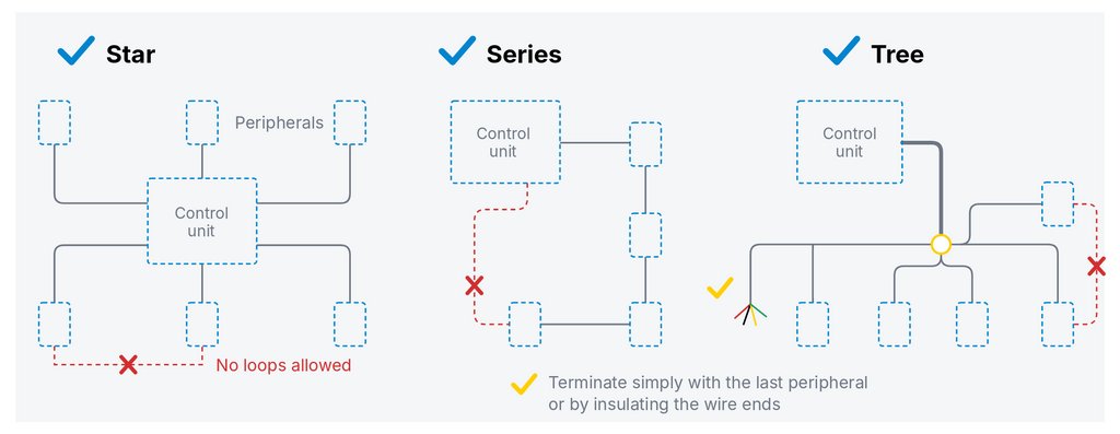
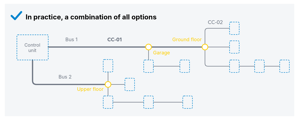
The bus can run in series, as a tree or as a star. A proven approach is to run backbone branches from the control unit, which then split further at a suitable node (for example in the corridor on each floor).
Original splitters are available, but any other reliable connection can be used (twisting, soldering, Wago lever terminals...). The node can be placed in a deep flush-mounted box or in a JABLOTRON surface-mounted installation box suitable for the original splitters.
If the layout makes it advantageous, several devices can be connected one after another. However, any break in the cabling then affects the entire series, so there should not be too many devices in a row.
What to watch out for
The bus must never form a loop. A branch must not return to the backbone or connect to another branch. The end of a line is either terminated by a peripheral or the cable is simply insulated. No terminating resistor is used.
Each control unit bus (JA-103K = 1×, JA-107/8K = 3×) can have a maximum of 60 devices connected. Peripherals with high communication demands (keypads, photo PIR detectors, radio module…) should not exceed 10 in total on one bus.
Avoid long parallel runs with power cabling. Bus cabling should be run together with other communication / low-voltage installations, separately from power cabling.
If the bus leaves the protected area, for example to a separate building such as a garage or shed, it should be protected by a JA-110T isolator on the inside, towards the control unit. The isolator protects the main part of the installation from a fault being carried in.
-
Cable: CC-01 (backbone) / CC-02 (branches), or UTP/SYKFY
-
Max. length 500 m per bus, up to 3 buses, JA-120Z booster for extension and more peripherals
-
Topology: in series, tree, star — never a loop
-
A maximum of 60 devices per control unit bus output
-
JA-110T isolator where the bus leaves the protected area
4. Wireless solutions
Range
The range of radio communication at 868 MHz cannot be expressed universally as a single number; it always depends on the environment and the specific conditions.
-
Laboratory conditions (comparison with other systems): up to 3,000 m
-
Ideal real outdoor environment without obstacles (e.g. an airfield): up to 1,000 m
-
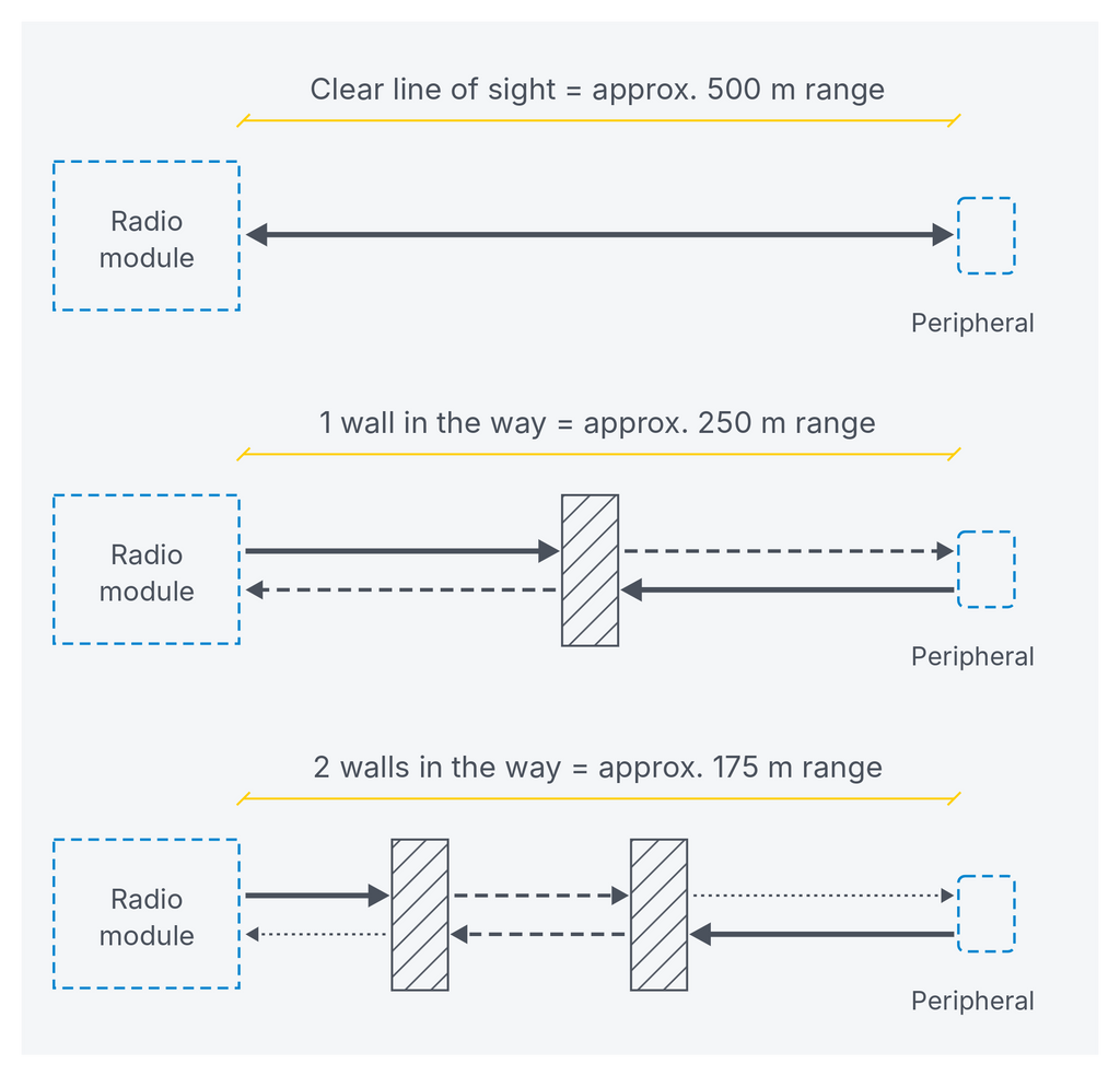
Typical outdoor environment, with reflections from buildings, fences or undulating terrain: up to 500 m
-
Indoor environment: every wall reduces the range, roughly by half. A solid stone or reinforced concrete wall limits the range considerably more than a plasterboard partition or YTONG.
In practice, this means that one radio module placed in the middle of a typical brick house reliably covers the entire house, the garden, the driveway and outbuildings such as a garage or garden shed.
Larger or complex buildings
As standard, the radio module is located directly in the control unit (JA-10xKR control unit kit). This is sufficient for a typical building.
If for some reason placing the module in the control unit is not suitable, it can be removed from the control unit and, using the PLV-JA111R kit, placed anywhere the bus runs. The centre of the building, for example a central corridor or hall, is ideal for the most even coverage.
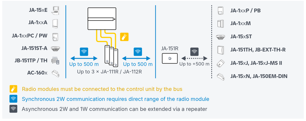
In this way, up to 3 radio modules can be installed in one system, covering even extensive or structurally complex buildings.
Signal repeater
The JA-151R repeater helps where the bus cannot be brought to the radio module. It repeats the signal from peripherals at full power, up to doubling the distance between the radio module and selected detectors.
The repeater is used mainly for extensive outdoor perimeters or buildings such as logistics or production halls.
Note: The repeater does not support fully bidirectional peripherals such as keypads, sirens, combined detectors with a camera or microwave, etc.
Battery life
Depends on the type of device, how often it is activated and its settings.
-
Simple motion or opening detectors: 5 years or more
-
Detectors with a camera, smoke detectors with a siren and other more energy-demanding devices: around 3 years
-
Keypads: typically 1.5 to 2.5 years
Keypads can be supplemented with an external 12 V power supply. The batteries then serve only as a backup in the event of a power failure and are replaced preventively, after about 5 years.
-
Range: typically up to 500 m outdoors, each indoor wall roughly halves the range
-
Up to 3 radio modules in the system, can be moved outside the control unit (PLV-JA111R)
-
JA-151R repeater doubles the range where the bus cannot be brought
-
Battery life: 5 years (basic detectors), 3 years (more demanding), 1.5 to 2.5 years (keypads)
5. Control unit and related modules
Small or large control unit
The control unit is the cornerstone of the entire system. Its choice also affects what needs to be prepared.
-
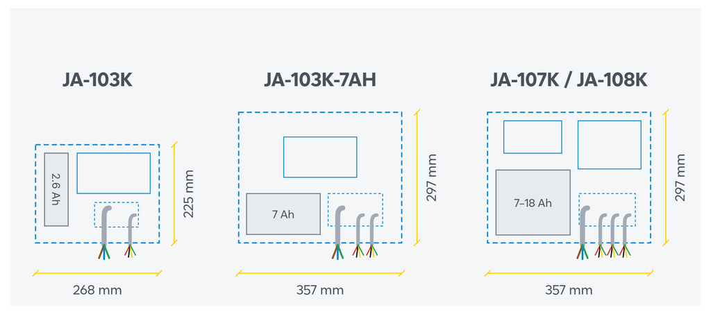
JA-103K is suitable for the smallest bus systems (10 peripherals) or medium-sized wireless systems (50 peripherals), typically flats and small commercial premises. The box measures 268 × 225 × 83 mm.
-
JA-103K-7Ah is suitable for medium-sized, primarily bus or hybrid systems where the smaller capacity of 50 peripherals is sufficient but a larger battery is needed for power backup. The box measures 357 × 297 × 105 mm.
-
JA-107K / JA-108K are suitable for large bus (up to 230 peripherals) and wireless (up to 120 peripherals) systems, such as larger family homes, companies, schools or hotels. They have up to 3 independent buses and a battery of up to 18 Ah. The box measures 357 × 297 × 105 mm.
Connectivity
The control unit needs to communicate on up to 4 levels:
-
GSM / LTE communicator, providing independent communication over mobile networks. It works even during a power or internet outage in the building. The communicator is fitted directly in the control unit on a dedicated connector.
-
LAN communicator is a fixed part of every control unit. It provides data communication via the building's internet connection. Using it is not essential, but we strongly recommend it: it speeds up the control unit's communication and adds a second path, independent of GSM.
-
Bus, providing communication with and power to bus peripherals, see chapter 3. Large control units (JA-107K, JA-108K) offer up to 3 independent bus connections; small control units (JA-103K, JA-103K-7Ah) have only one full-featured bus.
-
Radio module, providing communication with wireless peripherals, see chapter 4. The module can be installed directly in the control unit (JA-10xKR kits) or anywhere on the bus in the building.
Control unit location
Place the control unit where an intruder cannot easily reach it immediately after entering the building. It should be covered by a detector with an instant response, so that the alarm is triggered and transmitted before the intruder has time to damage the control unit.
The installation location should have the best possible GSM signal and a temperature without extreme fluctuations.
Although the control unit itself has no controls, think about accessibility for servicing and maintenance (the USB connector on the underside and space to open the cover).
-
Suitable location: a technical room above ground level, a server room, a study on an upper floor...
-
Unsuitable location: an entrance hall, reception, an unheated attic, a cellar, a basement below ground level...
Cable preparation
Bring all backbone branches of the bus cabling to the control unit installation location (see chapter 3).
For the power supply, prepare a CYKY-J 3×1.5 cable with 6 to 10 A circuit protection. Supply the control unit from a separate circuit with its own circuit breaker, so that a fault in another device does not cause the security system to fail.
For the internet connection via the LAN communicator, prepare a UTP cable (CAT 5 is sufficient), run from the rack or home router.
Connection to other technologies
If cabling can be run, prepare a bus cable between the control unit (or a suitable splitter) and technology nodes such as the electrical distribution board, rack, underfloor heating manifold, boiler room, garage, etc. Even if it is not planned in the first phase, the connection may be useful in the future for automating lighting and heating, linking to a camera system, a smart home and so on.
-
JA-103K: 268 × 225 × 83 mm, 1 bus
-
JA-103K-7Ah: 357 × 297 × 105 mm, 1 bus, battery up to 7 Ah
-
JA-107K, JA-108K: 357 × 297 × 105 mm, up to 3 buses, battery up to 18 Ah
-
Power supply: CYKY-J 3×1.5 cable, 6 to 10 A circuit protection, separate circuit
-
Good GSM signal at the installation location (avoid cellars, basements below ground level, etc.)
-
LAN for internet connection
-
A location at room temperature, difficult for an intruder to reach
6. Keypads and readers
Keypad layout
Keypads and readers are the main interface between the system and the user. They must be conveniently and intuitively accessible for easy operation.
Place a control keypad on all usual access routes into the building. In family homes, this is typically the entrance hall or hallway, but also the garage. In companies, besides the main entrance, also think of the staff rear entrance, the loading dock, etc.
For user convenience, add secondary keypads that make everyday situations easier. In a house with more than one floor, a keypad in the upstairs corridor is useful for arming the night mode in the evening; in a company, a keypad by the archive or server room saves a trip to the main keypad at reception.
Keypad features
The system should always have one main keypad with a display (e.g. JA-116E / JA-115E / JA-114E). A display keypad allows full control of all sections and user settings such as blocking users or peripherals, and shows details of an alarm or fault even if connectivity with the app is lost.
Secondary keypads can have much simpler functions, typically single-purpose control of arming of the adjacent section (e.g. JA-118E, JA-113E, JA-121E, JA-123E).
Access card readers
Stand-alone card readers (e.g. JA-119E, JA-112E, JA-120E, JA-121E), typically used for passing through doors, are installed, unlike control keypads, on the outside of the door, as close as possible to where it opens, so that passage feels natural.
On the inside, it must remain possible to pass through mechanically, using the handle, so that the building can be left even if the system fails, for example in a fire.
Installation preparation
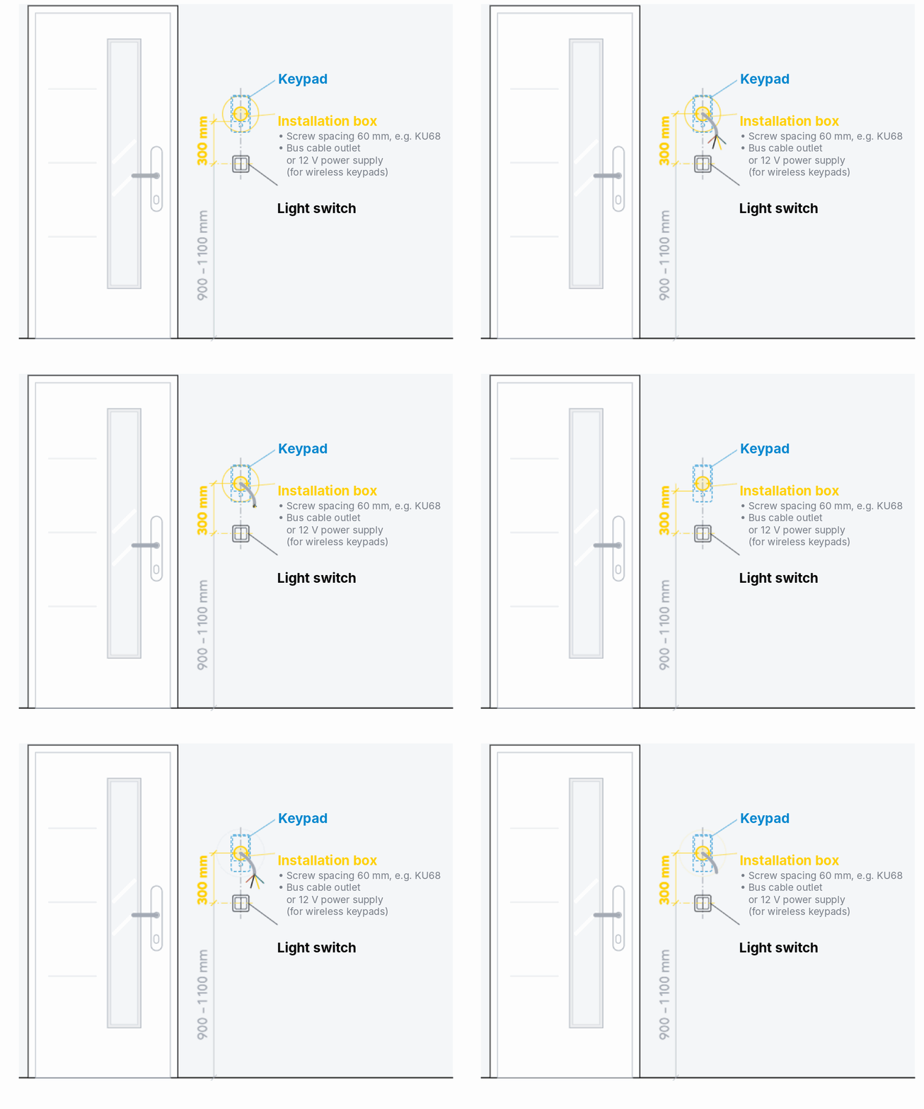
For both keypads and readers, the recommended mounting height is approximately 30 cm above the level of the light switches. Prepare a flush-mounted installation box with 60 mm screw spacing, for example KU68, to make mounting and wiring easier.
Cabling and power supply
For bus products, it is sufficient to bring the bus cabling to the box; the keypad is also powered from it. Keypads are the most demanding of all peripherals in terms of both power and communication. If there are several in the building, divide them evenly between the individual buses.
For wireless keypads, we recommend preparing an external 12 V power supply, for example from an adjacent light switch or socket using a power supply from the JABLOTRON range.
If power cannot be brought in, the keypads also work purely on batteries (except the JA-156E touch keypad). In that case, expect shorter battery life than for other peripherals (approximately 1.5 to 2.5 years) and the backlight going to sleep.
-
A keypad on every usual access route into the building
-
At least one keypad with a display for advanced user functions, ideally a bus keypad
-
Card readers on the outside of the door, always a mechanical handle on the inside
-
Mounting height 30 cm above the switches, installation box with 60 mm spacing (KU68)
-
Divide multiple bus keypads and readers evenly between the buses
-
For wireless keypads, ideally prepare a 12 V power supply
7. Sirens
Indoor sirens
Indoor sirens have a dual purpose. They make the intruder's stay unpleasant and at the same time warn users of danger, for example a fire or a break-in while they are asleep.
Place them so that the alarm sound and additional audio signals (doorbell, entry delay…) are audible throughout the building. In a family home, the hall or staircase is ideal; in companies, the central corridor or the area by the lifts.
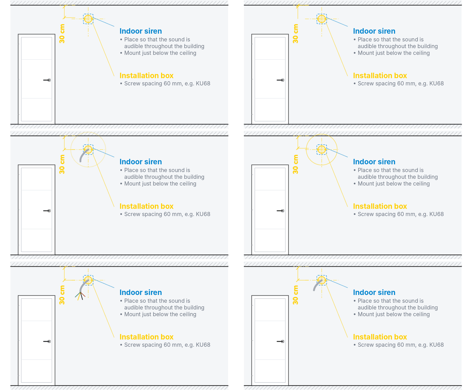
The indoor siren is mounted on the wall, usually just below the ceiling (e.g. 20 cm), so that it is not easily accessible to an intruder. Prepare a flush-mounted installation box with 60 mm screw spacing, for example KU68, to make mounting and wiring easier.
Outdoor sirens
Look for a location that is clearly visible from public space, for example from the street. The siren's job is not only to sound and flash during an alarm, but also prevention. A visible siren signals that the building is protected, and the intruder will rather choose another target without an alarm.
The ideal location is from first-floor height, i.e. at least 3 m, so that the siren cannot be reached easily. Typically the top of the gable, aligned with the upper edge of the upstairs windows, etc. Besides appearance, also think about protection from sun and rain. Although the design is ready for harsh outdoor conditions, where possible we recommend placing the siren so that, for example, the roof overhang helps protect it from sun and water ingress.
Installation and cable preparation for bus sirens
For bus sirens, use the same cable as for other bus peripherals (see chapter 3). An optional backup battery ensures full acoustic output and an alarm even if the bus is cut. For buildings at Security Grade 2 and 3, the battery is essential.
Indoor sirens:
-
For the JA-110A II, prepare a flush-mounted installation box with 60 mm screw spacing (e.g. KU68); it makes final mounting and wiring easier.
Outdoor sirens:
-
The JA-113A siren does not require any special preparation; the cable is simply brought out of the plaster at the installation location.
-
The siren detects cover opening, removal from the facade and loss of communication with the control unit. It therefore responds to any tampering attempt immediately with an alarm.
-
We recommend connecting it behind a JA-110T isolator. It ensures that a short circuit on the bus, caused deliberately or by water ingress, does not spread to the rest of the system inside.
Wireless sirens
The wirelessly communicating, externally powered JA-150A II siren requires a 230 V connection. Mains power ensures maintenance-free operation. Prepare a suitable power cable, e.g. CYKY-J 3×1.5, terminated in an installation box.
The fully wireless, battery-powered JA-154A and JA-163A sirens require no preparation. They are simply screwed to the required location; power is provided by batteries.
-
Indoor siren: audible throughout the building, mounted below the ceiling, prepare a box with 60 mm spacing (KU68) for bus versions
-
Outdoor siren: clearly visible from public space (prevention), mounted as high as possible, ideally behind a JA-110T isolator
-
Bus, wirelessly communicating externally powered, and fully wireless battery-powered versions are available.
8. Motion detectors
Location
Use motion detectors to cover all larger rooms and areas where an intruder is likely to move during a break-in, or where other functions such as lighting need to be automated based on motion.
Basic motion detectors (JA-110P, JA-112P and their combined equivalents) have a recommended mounting height of 2.5 m ± 10 cm for reliable coverage. They are most often installed in the corner of a room; mounting on a flat wall is possible if a corner is unsuitable for some reason.
Choose a location where no furniture will block the view in the future, e.g. the area above the entrance to the room.
What to watch out for
PIR detection is sensitive to sudden temperature changes and to the movement of objects at a temperature close to that of the human body, including warm air currents. Avoid:
-
placement above radiators, above poorly sealed windows or windows that remain open for ventilation after everyone has left the building, especially if the windows have curtains or net curtains that can move in a draught
-
proximity to sources of air flow, such as air conditioning or ventilation outlets
-
proximity to sources of radiant heat, such as fireplaces or stoves
-
sunlight dazzling the detector lens, typically at sunrise or sunset; watch out for placement facing large glazed areas oriented east or west
If any of these conditions cannot be met, use a combined PIR + MW detector instead of a basic PIR detector (JA-121PW, JA-161PW, JA-122PW or JA-162PW). PIR triggers are additionally confirmed by a microwave sensor working on the radar reflection principle, which ensures resistance to temperature influences.
Range and detection angle
The specific coverage parameters differ slightly between individual detectors depending on the type. In general, the detection angle is from 90° and the range from 10 m. A single detector installed in a corner therefore reliably covers a room of typical size.
Cable preparation
For a bus detector, bring the cabling out of the plaster at the installation location, typically directly in the corner. Under the plaster, the cable should run up or down the corner as precisely as possible, so that there is no risk of drilling into it during installation: the detectors are screwed on at the edges resting against the walls, approx. 3 cm from the corner. If the ceiling height is 2.6 m or less, the cabling can also be brought out of the suspended ceiling, i.e. through the ceiling directly in the corner. During installation, the detector is placed as close to the ceiling as possible and the cabling remains hidden.
For detectors with basic PET immunity, a different recommended height applies: 2.2 m. Certain further restrictions apply to the use and placement of PET detectors; details can be found in a separate article.
Ceiling mounting
For corridors, garages, large offices and other areas where corner or wall mounting is not suitable, a ceiling PIR detector with a 360° detection angle is available, JA-115P or JA-155P. The range is a radius of 4.5 m at a ceiling height of 2.5 m and 5.5 m at a ceiling height of 3.5 m. For ceiling mounting, the cable is simply brought out through the ceiling in line with the detector installation, typically aligned with smoke detectors and light fittings.
Extended versions
-
PIR + camera (JA-120PC (90), JA-160PC (90), JA-122PC, JA-162PC): automatically attaches a photo of whatever triggered the alarm; a photo can also be requested manually at any time.
-
PIR + glass break (JA-121PB, JA-161PB, JA-122PB, JA-162PB): in rooms with large glazed areas, it also offers an independent glass breakage detector in a single product.
Wireless versions
All motion detectors are also available as wireless versions. In basic PIR detectors, batteries typically last 3 to 5 years; in detectors with a camera around 2 years, depending on how often photos are taken and the illumination setting.
Outdoor solutions
Outdoor detectors catch an intruder before the first damage to windows or doors. Cover in particular places with a high risk of being chosen by an intruder to enter the building, typically the entrance from the garden, the delivery entrance, etc.
Our range includes the wireless outdoor detectors JA-157P, JA-158P and JA-159P, combining high-quality OPTEX detectors with our JA-150TX-UNI interface. The interface can also be purchased separately and fitted into another suitable detector, depending on the needs of the specific application.
For a bus solution, use the miniature JA-111H TRB module, which is inserted directly into detectors from other manufacturers and responds to alarm, tamper, masking and fault, which it transmits digitally from the detector over the bus. For bus installation of outdoor detectors, use a JA-110T isolator to separate the outdoor wiring.
-
Mounting height: 2.5 m ± 10 cm (corner or wall), 2.2 m for detectors with basic PET immunity
-
Detection angle from 90°, range from 10 m (varies by type)
-
Avoid: radiators, leaky/open windows, draughts, air conditioning, radiant heat, dazzling sunlight
-
Solve problem locations with a combined PIR + MW detector
-
Ceiling mounting (360°): JA-115P / JA-155P, range 4.5 to 5.5 m depending on ceiling height
-
Extended versions: PIR + camera, PIR + glass break
-
Wireless battery life: 3 to 5 years (basic PIR), approx. 2 years (with camera)
9. Opening detectors
Location
The detector consists of a sensor mounted on the frame and a permanent magnet mounted on the sash. The sensor and magnet should be approximately 1 to 5 mm apart. They must not touch; final installation is ideally carried out only on adjusted windows / doors after the rest of the construction work is complete.
For installations at Security Grade 2 or 3, the magnet must be positioned so that opening is detected at the slightest movement of the sash: it is mounted in the upper part of the window. In installations without a security grade requirement, the magnet is sometimes placed at the bottom in practice, so that the window can be left tilted open for ventilation and only full opening is detected. Typically in bedrooms, bathrooms, etc.
Concealed detectors
If you are building or renovating, it is ideal to use original concealed magnetic detectors from the window / door manufacturer, installed during manufacture. Alternatively, SA-211 or SA-210 recessed detectors can be fitted when the windows are installed on site. They are drilled directly into the frame, and the cable is run through the frame out into the window reveal, where it is hidden under the plaster after connection. The entire solution is thus completely invisible in the interior.
Because of their miniature size, concealed wired detectors are analogue and unpowered. To connect them to the system, they must be wired in a star to a suitable input module, which digitises their state and communicates it to the system over the bus or wirelessly, with a separate address for each input.
Input modules and wiring
-
JA-112M: 2 inputs, own enclosure
-
JA-114HN: 4 inputs and 4 outputs, for the control unit or a surface-mounted box
-
JA-118M: 8 inputs, for the control unit, a surface-mounted box or a flush-mounted box (e.g. KU68)
-
JA-116H: 16 inputs, for the control unit or a surface-mounted box
-
JA-162M: 2 inputs, wireless version for a surface-mounted box
-
JA-150M: 2 inputs, wireless version with its own enclosure
Input modules are installed either directly in the control unit or in an original JABLOTRON box (JA-195PL or JA-194PL), which provides tamper protection in line with the requirements of the standard. A proven and elegant solution in practice for installations without a Security Grade 2 or 3 requirement is the miniature eight-input module JA-118M. It can also be installed in a flush-mounted box: the cabling from up to 8 windows is run by the shortest route to the flush-mounted box, where it is connected to the JA-118M module, which is connected to the bus. The box is closed with a cover and can be hidden, for example, behind furniture. Several modules are installed in this way, suitably distributed to cover the whole building.
As the cable, use the standard CC-02 or CC-01 or similar, see chapter 3 (JABLOTRON bus). When the windows are installed, the original cable from the concealed detector is brought out of the frame and connected under the plaster near the window to an extension leading to the input module. For a concealed detector, we recommend leaving a 20 cm cable reserve in the window frame so that it can easily be pulled out if it needs to be replaced.
A wireless alternative for concealed mounting is the JA-152M detector, suitable for uPVC or wooden Euro windows. It is installed directly in the frame, in the space between the inner and outer seals. However, because the detector sits between the metal parts of the frame and sash, its radio range may be adversely affected. The concealed detector may therefore not work over the same distance as surface-mounted detectors: it is best suited to smaller buildings such as a flat or family home.
Surface-mounted detectors
Surface-mounted detectors are usually used if the windows are already installed and the concealed version with cabling through the window frame cannot be used. The cable is brought out of the plaster at the installation location through the window reveal and led to the detector on the surface.
Surface-mounted detectors are available directly as bus versions (JA-115M, JA-113M). They can therefore also be wired in series or in any other way, like other bus peripherals. However, given their small size and visible cabling, series wiring, with one cable going in and another going out, is neither very convenient nor aesthetic. A better solution is usually to branch the bus in each room, for example in the suspended ceiling, and run a separate cable to each detector, or to branch off from an adjacent motion detector, etc.
If the cable cannot be brought to the detector neatly, the wireless alternative is used (JA-155M or JA-153M), even where the rest of the installation is wired. The batteries in these detectors typically last 3 to 5 years or more.
Security Grade 3
For installations at Security Grade 3, the JA-113M and JA-153M detectors are available. In addition to opening, they also detect an external magnetic field, preventing the detector from being defeated by holding another magnet against it. For this mode, the detectors require calibration during installation: repeated opening and closing against the specific counterpart. Installation must therefore be carried out only after the windows have been finally adjusted.
Outdoor and heavy-duty solutions
For locations such as garage doors or entrance gates, heavy-duty outdoor sensors are available:
-
SA-220: drive-over, floor-mounted, typically for sectional doors
-
SA-204: metal, for standard mounting on a frame or leaf, typically for a sliding or swing gate or a garden gate
These detectors must also be connected to an input module, either close to the detector (bus: JA-112M, wireless: JA-162M, JA-150M) or at a greater distance, for example using a free input of a JA-118M in the adjacent part of the building.
-
Sensor and magnet: distance 1 to 5 mm, magnet at the top for Security Grade 2/3, at the bottom if ventilation is required in the armed state (does not meet a security grade)
-
Concealed detectors: original from the window manufacturer, or retrofitted SA-211 / SA-210, connected to the system via an input module (JA-112M, JA-114HN, JA-118M, JA-116H, JA-162M wireless)
-
Wireless concealed version: JA-152M, for Euro windows, shorter range
-
Surface-mounted bus: JA-115M, JA-113M, series wiring possible, but star wiring is better to prepare
-
Surface-mounted wireless: JA-155M, JA-153M, JA-150M, batteries 3 to 5 years or more
-
Security Grade 3: JA-113M, JA-153M, detection of external magnetic field, calibration required
-
Industrial: SA-220 (drive-over), SA-204 (metal), connected via JA-112M / JA-162M / JA-150M
10. Glass breakage detectors
Detection principle
The detector responds to the characteristic combination of a pressure change and high sound frequency when glass shatters. It can be used for glazed areas from 60 × 60 cm, but is particularly useful as a supplement for larger areas, such as French windows or shop windows, through which an intruder can easily enter once they are broken. For ordinary smaller windows, opening detection is more suitable: if a small hole is cut or broken out to reach the handle, the glass breakage detector may not respond, unlike the subsequent opening of the sash, which a magnetic detector covers reliably.
Especially for large glazed areas facing a busy street, external stimuli may in certain situations (typically New Year's Eve celebrations) cause a false alarm. Glass breakage detection should therefore be combined with another principle, for example motion detection, which confirms any entry inside (the system allows a condition of confirmation by another detector to be set).
Stand-alone or combined
A stand-alone detector (JA-110B) is suitable for situations where the PIR detector in the adjacent area is not suitably placed: for example, it is too far away, it is on the same wall as the window, around a corner out of direct view, etc.
In other cases, a combined detector with PIR is ideal: JA-121PB, JA-161PB, JA-122PB, JA-162PB (see chapter 8, Extended versions). In one product and with a single installation, it provides 2 independent functions.
Location
The ideal distance of the detector from the glass is 1.5 m to 9 m. Place it on the opposite wall, just below the ceiling (e.g. 30 cm), directly facing the glazed area. Alternatively, it can be placed on the ceiling in line with the glazed area.
There must be no acoustic obstacle, such as a heavy curtain, between the detector and the glazed area.
Cabling and power supply
The wiring is the same as for other bus peripherals. The bus can continue in series from the detector, or that bus branch can be terminated in it (see chapter 3).
For the stand-alone JA-110B detector, bring the cabling out of the plaster at the bottom of the detector. The mounting holes are located on the detector's axis above the cable opening. Under the plaster, therefore, run the cable to the detector either from below or from the side. If the cable has to be run from above, the detector can also be installed upside down (it must be at least 10 cm from the ceiling to allow access to the opening latch).
For combined detectors, the same recommendations apply as for motion detectors, see chapter 8.
-
Stand-alone: JA-110B (bus only)
-
Combined with PIR: JA-121PB, JA-161PB, JA-122PB, JA-162PB (bus and wireless)
-
Suitable for glazed areas from 60 × 60 cm
-
Placement on the opposite wall below the ceiling or on the ceiling, distance from the glass 1.5 to 9 m
-
No acoustic obstacle between the detector and the glass
-
Recommended in combination with motion detection to confirm entry
11. Fire detectors
Use
Requirements for fire detection may vary according to local legislation and the type of building. We will not discuss premises where a fire alarm system (EPS) is mandatory (hotels, shopping centres, etc.), which fall into a separate field, but will focus on practice in smaller private buildings, where installing fire protection is largely voluntary and can also be implemented as part of the alarm.
Unlike a mandatory stand-alone smoke alarm, which simply beeps when it detects smoke, a solution built on integration into the security system is considerably more advanced, closer to full-scale fire alarm systems:
-
Detectors with a built-in sounder (JA-111ST-A, JA-151ST, JA-151ST-A) not only meet the requirements for a stand-alone smoke alarm, and are thus sufficient for final building approval, for example, but in addition to their own beeping also sound the system keypads and sirens and, above all, notify the user and the Alarm Receiving Centre remotely.
-
Various automatic actions can be linked to a fire alarm, for example starting smoke extraction ventilation, opening skylights or unlocking emergency exits.
-
Detectors without a sounder are also available (JA-110ST, JA-150ST), a less expensive alternative suitable for covering additional places where only a system response is needed, without a stand-alone function requirement.
-
Detectors with a system siren function (JA-1x1ST-A) can also sound for events other than their own alarm and, in installations without a security grade requirement or additional audio, can also take over the function of an indoor siren.
Ideal coverage
Place a detector in every room with a fire risk. The higher the risk, the more a detector should be there, to detect a fire as early as possible, even behind a closed door:
-
Kitchens and living rooms: risk from cooking, a fireplace, a stove or the Christmas tree
-
Technical rooms and garages: ignition of technical equipment, batteries, stored flammables
-
Bedrooms and children's rooms: a fault in the electrical installation or ignition of personal electronics being charged
Minimum coverage
For residential buildings, legislation in the Czech Republic (Decree No. 23/2008 Coll.) requires at least one detector with a stand-alone function in the part leading to the building exit, i.e. in the entrance hall, hall or central corridor. Compliance is a condition for final building approval.
For buildings with a floor area over 150 m² or more than one floor, an additional detector must be added in another suitable part, typically above the staircase on the upper floor.
Usual coverage
In practice, a combination of both approaches is most common: separate detectors in the highest-risk rooms (living room with kitchen, technical room, garage) and a detector in the connecting corridor, or also on the upper floor above the staircase in a house with more than one floor.
Location
There is no universal rule for the exact location in a room. The usual practice is the centre of the ceiling in line with the light fittings, which is fine for smaller rooms, but it always depends on how the air flows through the space: smoke must reach the detector as soon as possible and must not be pushed away from the detector by fresh air.
-
If the room has an air supply, for example from a heat recovery ventilation unit, place the detector in the path of the air flow towards the door, through which the air continues to the extraction.
-
In rooms with a staircase, gallery or other connection leading upwards, bear in mind that warm smoke naturally rises. The detector should be close to where the ceiling ends and the air flows further upwards.
What to watch out for
-
Keep a distance of at least 0.5 m from any wall, partition or other structure: air circulates poorly in a corner.
-
In rooms with a sloping ceiling, the detector must not be at the very apex (ridge, point where it meets the wall). Keep a distance of 0.9 m from the apex on the horizontal axis.
-
Never hide the detector in recesses, right behind light fittings or other protruding structures, and do not try to recess it into a suspended ceiling. A pocket of warm air or an obstacle to air flow can slow down smoke reaching the detector.
-
Do not use detectors in rooms with a ceiling higher than 5 m: the smoke disperses and cools before it reaches the detector.
-
Avoid proximity to ventilation or air conditioning outlets, which can blow smoke away from the detector. For a perforated ceiling, keep a distance of 0.6 m from the perforation.
-
Do not use detectors in dusty areas (warehouses, production, workshops), smoking rooms or places where steam occurs (bathrooms, the area directly above a hob or oven). Dust or water particles can cause false alarms and shorten the detector's service life.
Cabling and power supply
For bus detectors, the same rules apply as for other bus peripherals; they can be wired in series, as a star or as a tree (see chapter 3). The cable is simply brought out directly from the plaster or suspended ceiling on the detector's vertical axis. The round shape and the pair of mounting holes with 85 mm spacing provide enough space to bring the cable through the plaster from any side.
The batteries in wireless detectors, or in bus detectors with a stand-alone function (where the battery serves as a backup in case of system failure), last 3 to 5 years or more, depending on the frequency of false alarms.
-
Detectors with a sounder (stand-alone function): JA-111ST-A (bus), JA-151ST, JA-151ST-A (wireless)
-
Detectors without a sounder (system response only): JA-110ST (bus), JA-150ST (wireless)
-
Ideal coverage: kitchen, living room, technical room, garage, bedroom, children's room
-
Minimum coverage under Decree 23/2008 Coll.: escape route (entrance hall, hall, corridor), additional detector for floor area over 150 m² or more than one floor
-
Location: centre of the ceiling, in the direction of air flow, min. 0.5 m from the wall, min. 0.9 m from the apex of a sloping ceiling
-
Unsuitable: ceilings above 5 m, proximity to ventilation, dust, smoke, steam
-
Cabling: same as other bus peripherals, cable outlet on the detector's axis
-
Battery life: 3 to 5 years or more
12. Flood detectors and water shut-off
Location
Ideally, detectors are placed wherever an appliance is connected to the water supply (washing machine, water heater…) or where there are high-risk fittings and connected parts (taps, valves, filtration…). Connection hoses and seals age over time and can fail. Hoses are the highest risk, as they fail suddenly and cause a larger leak.
The most common uses of flood detectors:
-
Behind the washing machine
-
Behind the dishwasher and under the kitchen sink, or behind an American-style fridge
-
Under the vanity unit in the bathroom
-
Under the water heater and at the main water supply in the technical room.
Versions
3 versions are available:
-
JA-151F, wireless. It is placed behind the appliance or attached to the wall using a self-adhesive magnet, which also allows it to be easily removed for cleaning. The detector requires no preparation or drilling during installation. It is particularly suitable for home installations.
-
JA-110F, bus. It is mounted on the wall or floor; the sensing probes must be right at floor level. It has a fixed 2.5 m cable lead, which is run, for example, to a flush-mounted box at socket height into which the bus is brought, or to a nearby peripheral, etc. Because of the visible cable, it is mainly suitable for hidden or technical areas.
-
LD-81 + JA-150M, a combination of a wired sensor and a module with universal inputs acting as a transmitter. The sensor is placed at the point of detection and the 2.5 m cable is connected to the JA-150M. Suitable where there is no bus and the sensor will have no access for battery replacement (for example under a Geberit concealed cistern), or where a fixed screw mounting is needed, which the JA-151F does not allow (e.g. areas with public access)
Limitations
All the solutions listed are intended for emergency detection. They cannot be used in places with a risk of permanent flooding or in aggressive substances, such as septic tanks or rainwater tanks. For these applications, use a suitable analogue level or float switch with a normally open or normally closed contact. The switch output can be connected to any input module, in the same way as an analogue magnetic detector (see chapter 9).
Connection to a smart valve
Connection to a smart valve not only provides an immediate response to a water leak, i.e. immediate shut-off of the supply even when the occupants are away, but also works preventively: it shuts off the water automatically when the alarm is armed and opens it again on arrival. When no one is home, this eliminates the risk of a larger leak even in places not covered by detectors.
We recommend the Peveko smart valve, which can be powered directly from the system bus, so that it works even during a mains power failure in the building.
Valve preparation
As preparation, bring the bus to a point near the valve installation location, typically to a JA-190PL surface-mounted box or similar. The valve has a fixed 2.9 m cable lead, which is run to the box and connected, for example using a suitable splitter.
-
Detector location: behind/under high-risk connections (washing machine, dishwasher, sink, washbasin, water heater, main supply)
-
JA-151F: wireless, placed down or attached with a magnet, no preparation
-
JA-110F: bus, 2.5 m cable, mounted on the wall or floor, probes at floor level
-
LD-81 + JA-150M combination: for places without a bus and without access to the sensor for battery replacement, or when a fixed screw mounting is needed
-
Standard detectors cannot be used for permanent flooding / aggressive substances: use an analogue level/float switch via an input module
-
Peveko smart valve: responds automatically to system events, powered from the bus, 2.9 m cable to the box (e.g. JA-190PL)
13. IP cameras and NVR
Ideal coverage
Ideally, the cameras' field of view should cover the entire outer perimeter of the house as well as all access routes to the cameras themselves, so that an intruder cannot cover or damage one camera after another unnoticed.
For a rectangular house, 4 cameras are typically sufficient, one at each corner, monitoring the adjacent wall and the area towards the next camera. If the shape of the house is more complex, or the surroundings of outbuildings (garden shed, garage) also need to be covered, more cameras are usually needed for a complete overview without blind spots.
As long as cabling can be run, always plan for the ideal coverage scenario, i.e. bring a cable to all potential locations, even if only some of them end up being used. A wireless retrofit solution is problematic for cameras: a camera always needs at least an external power supply; purely battery operation is not possible.
Practical compromise
In practice, often only the highest-risk places are covered:
-
The area between the street and the house, including the entrance or garage driveway, to see who is arriving on foot or by car
-
The area behind the house towards the garden, typically where the terrace and French windows are, where the risk of a break-in is highest
-
The area by the shed or garden house, which are frequent targets
The field of view angle is specified for all cameras, so when drawn on a floor plan, it is easy to imagine everything the camera will see from a given location. For JABLOTRON cameras, count on a 91° field of view.
Location
-
If there is a choice, the camera should be at least 4 m above ground level, for an overview from above and protection against damage or covering.
-
A location sheltered from direct sunlight and rain is ideal, for example under the roof overhang.
-
Distance from lightning conductors according to the building's specific protection class, universally at least 0.8 m.
-
Avoid inside corners: a cobweb in the corner significantly limits the view under night-time illumination.
-
At least one camera should be clearly visible from the street, for its preventive effect.
Cabling
For cameras, use UTP or FTP cabling, ideally CAT6, although older CAT5 can also be used. The cable carries both video and power via PoE.
The cabling is run in a star, a separate cable for each camera, to the location of the recording device (NVR). Ideally to a rack, where the cabling is terminated in a patch panel and only the ports actually used are connected with patch cables. Unused cabling remains in reserve.
In family homes, it is a good idea to install a small home rack, which also houses other IP equipment such as the home router and switch. We recommend backing up the NVR and router with a UPS, or a PV battery storage system, so that the cameras remain operational even during a 230 V outage and cannot be disabled by switching off the main circuit breaker from outside.
At the camera installation location, simply bring the cable directly out of the plaster, leaving an excess of at least 0.5 m. A junction box is installed under the camera, in which the UTP cable is connected to the camera's connection cable. If there is a cavity under the camera, for example when installing on a soffit, prepare a larger hole (e.g. 20 mm) that allows the excess cable, including the connector, to be pushed into the cavity and the camera to be installed without a junction box.
JABLOTRON cameras
The JI-113C, JI-114C and JI-114C-A cameras provide basic functions for undemanding users: live view, video recording and pairing of an alarm event with a video sequence directly in the MyJABLOTRON app. Cameras equipped with audio transmission (JI-11xC-A) can also deter an intruder with their own warning message combined with alarm flashing.
Using the JI-120T interface, other IP cameras supporting the RTSP protocol can also be connected to the JABLOTRON ecosystem, regardless of the manufacturer.
Thanks to the native solution, a static public IP address is not required.
Video recording
-
The most affordable solution is recording to an SD card directly in the camera. However, if the camera is stolen or destroyed, the recording itself is lost too.
-
Most commonly, a network video recorder (NVR) is used, which stores recordings, typically from 4 to 8 cameras, on a local disk, relatively securely inside the building.
-
The most secure option is parallel storage of recordings completely outside the building, directly in JABLOTRON Cloud. Cloud storage involves certain operating costs and is therefore suitable mainly for the highest-risk places / buildings, e.g. vault rooms, jewellers, etc.
Connection to the security system
We recommend also bringing a bus cable to the NVR installation location (to the rack), which allows the two systems to be connected together.
Cameras equipped with their own motion detection and an alarm output can be connected to the system using a suitable input module, for example JA-111H TRB, and used as outdoor detectors. Compared with standard PIR detectors, however, detection by cameras is better suited to informative motion notifications (without the siren sounding) and automation, for example of outdoor lighting.
In the opposite direction, cameras can be blocked when the system is disarmed, i.e. recording or transmission can be switched off at times when the occupants do not want it.
-
Ideal coverage of the entire perimeter, cameras watch each other, 4 cameras at the corners for a simple house
-
Compromise coverage: entrance/driveway from the street, rear of the house with the garden, shed/garden house
-
Mounting at least 4 m high, sheltered location, at least 0.8 m from a lightning conductor, not in inside corners
-
Cabling: UTP CAT6 (or CAT5), in a star to the rack with the NVR and patch panel, cable excess for the camera at least 0.5 m
-
Back up the NVR and router with a UPS/PV storage
-
Own cameras: JI-113C, JI-114C, JI-114C-A
-
Integration of third-party cameras (RTSP) via JI-120T
-
Connection to the system bus for motion notifications and automation of outdoor appliances
14. Door and gate opening
Principle of connection to the alarm
To control garage doors, gates, garden gates and doors, a simple analogue connection via PG output modules is used. Based on an authorised user command, from a keypad, reader, the MyJABLOTRON app or a remote control, the system switches a relay output connected to the appliance and opens it even without physical keys, including the option of remote control.
Garage doors and entrance gates
These are typically controlled by a short pulse, just like manual operation with a conventional wall push button in the garage. In response to the pulse, the door changes its state, usually in open / stop / close mode. Because of this pulse behaviour, it is advisable to also monitor the actual state of the door with a magnetic detector (see chapter 9), so that the user can clearly see, even remotely, whether the door is open or closed.
-
Bus installation: The JB-111N relay module is suitable for both doors and gates. Bring the bus all the way to the drive installation location. The relay is placed in a JA-190PL universal box next to the drive (indoor installation), or directly under the drive cover or in a suitable IP-rated box close by, from where it is wired to the control terminals (outdoor installation).
-
Alternative from the distribution board: if the maximum length of the control cabling allows it (check the manual for the specific drive), the JA-110N-DIN bus relay or the AC-160-DIN wireless relay can be placed directly in the distribution board. The relay is thus hidden securely inside the building and switches the drive input via a suitable cable with at least 2 cores running from the distribution board to the door / gate.
-
Wireless control of garage doors is neatly provided by the JB-162N-PLUG (French) or JB-163N-PLUG (Schuko) smart plug. It is plugged in ahead of the drive's power supply, and a pair of control wires is run to the control terminals. Installation is done within a minute without any building preparation. Details can be found in the article on the JABLOTRON portal.
-
Wireless control of entrance gates is typically implemented using the JA-151N module with a supply range of 12 to 24 V. It can therefore be powered directly from the drive's accessory output terminals. The module is placed directly under the drive cover or in a suitable outdoor box close by.
Electromotive control of entrance doors
Unlike doors and gates controlled by a potential-free input, for doors voltage is usually supplied directly to the motorised lock drive.
Ideally, plan for electric control at the door design stage. Manufacturers offer affordable solutions where the motorised drive is concealed directly inside the door mechanism from the factory. The cable is run from the door frame through the plaster to a suitable location, for example the distribution board or a JA-190PL universal box, where it is connected to the relay module.
Motorised locks usually require a 12 or 24 V power supply. Because of the higher current consumption, powering them directly from the bus is not suitable. Use a suitable external power supply whose output to the lock is switched by the relay module:
-
JA-110N-DIN / AC-160-DIN directly from the distribution board
Electromagnetic door strikes
To control access through interior doors in commercial buildings, or for outdoor garden gates, simple locks are usually used which release the latch when power is applied and allow passage even without pressing the handle.
Door strikes are available in low-voltage, low-consumption versions up to 500 mA / 12 V DC. They can therefore be powered directly from the bus, ensuring operation even during a power failure. For this solution, the JA-120N module is used, which uses batteries to absorb current consumption peaks.
For a wireless solution, the JA-151N module powered by an external 12 V power supply can be used.
Bring the bus and a pair of wires from the lock to a suitable place near the door. The connection to the relay module is made in a JA-190PL universal box or similar. Alternatively, the cabling from the lock can be run all the way to the distribution board, where the power from the external supply is switched using the JA-110N-DIN / AC-160-DIN.
-
Garage doors / gates (pulse): JB-111N (bus at the drive location), JA-110N-DIN / AC-160-DIN (switching from the distribution board), JB-162N-PLUG / JB-163N-PLUG (wireless solution for garage doors), JA-151N (wireless solution for outdoor gates)
-
Always recommended: add a magnetic detector to monitor the actual state of the door / gate
-
Motorised door locks (12/24 V, higher consumption): external power supply + JA-110N-DIN / AC-160-DIN (distribution board) or JB-111N / JA-151N (box near the door)
-
Door strikes (12 V, up to 500 mA): JA-120N powered directly from the bus (works even during a power failure), or JA-151N wirelessly with an external power supply
-
Connection always in a JA-190PL universal box near the door/gate, or centrally from the distribution board
15. Temperature control and measurement
Detailed information on how to connect JABLOTRON temperature control to the heating system in the building can be found in the article https://portal.jablotron.com/how-does-temperature-control-work-in-jablotron-100
Control principle
Thermostats (JB-111TP, JB-151TP, JB-111TH, JB-151TH) measure room temperature, humidity and, where applicable, floor temperature. The JB-112TP and JB-112TH thermostats also measure CO2 concentration. By comparing the measured and required values, the system switches the PG outputs assigned to heating, cooling or ventilation. The control unit also provides backed-up power to bus thermostats.
In practice, three basic approaches are used:
-
Local control: one thermostat controls a separate heat source in a smaller or separately handled area (bathroom, cottage, garden house).
-
Central control: a limited number of thermostats in reference locations control one common heat source for the whole building, typical of older houses.
-
Zone control: each room has its own thermostat controlling its own radiator, underfloor heating loop or direct electric heater, with minimal waste of heat.
Location
The same recommendations apply to the thermostat as to keypads:
-
mounting height 120 to 150 cm
-
out of direct sunlight, which would affect the measurement
-
away from windows whose leaks or being ajar would affect the measurement
-
an easily accessible place with no risk of being blocked by furniture in the future
In practice, this usually means placement above the light switches at the room entrance, with the thermostat's axis 30 cm above the axis of the switches.
Cable preparation
Bring the cabling out into a flush-mounted box with 60 mm screw spacing, into which the bus thermostat can be partially recessed. If a box cannot be prepared, the thermostat can also be surface-mounted: bring the cabling out of the plaster in the middle of the planned location, from above or below (the thermostat's mounting holes are on the product's horizontal axis).
The bus to the thermostats runs in series, as a tree or as a star, as with other peripherals. Thermostats are not protected by a tamper contact, so to meet Security Grade 2 they must be connected separately: behind a JA-110T isolator or on a separate bus output of the control unit, separately from alarm devices.
Preparation for the floor sensor
From the thermostat installation box, run a flexible conduit with a diameter of 15 to 20 mm into the floor, ending at the same height in the floor build-up as the heating. Place the end of the conduit at least 30 to 50 cm from the wall, midway between the underfloor heating loops, and seal it against screed ingress. If the heating is still being laid, leave an excess of conduit, for example 1.5 m, and leave the final shortening to the heating engineer. The sensor is pushed into the conduit only during final installation of the thermostat.
Connection to a specific heat source
-
Hot-water underfloor heating: JB-128N module, up to 12 independent circuits, controls NC 230 V thermoelectric actuators (max. 2 W) as well as the heat source and circulation pump. It requires the bus and a 230 V power supply (CYKY-J 3×1.5, 4 to 10 A circuit protection) brought directly to the underfloor heating manifold. The module can also switch the heat source (potential-free NO output) and the circulation pump (switched-phase output). Prepare suitable cable connections for these functions too.
-
Electric underfloor heating: a power relay according to the number of circuits, either JA-110N-DIN / AC-160-DIN in the distribution board (separate CYKY-J 3×2.5 supply per circuit), or the AC-160-C wireless relay on the circuit supply, or a JA-190PL box with a JA-150N or JB-110N module.
-
Radiators: the JB-128N module can also switch wired actuators on radiators (requires cable preparation). For a wireless retrofit solution without building preparation, JB-150N-HEAD valve heads are available. They last an entire heating season on 3 AA batteries.
-
Direct electric heaters: the JB-164N-PLUG / JB-165N-PLUG smart plug with consumption metering and a load capacity of up to 16 A / 3,600 W.
-
Central heat source (boiler, heat pump): control via the appliance's potential-free terminals, most simply and wirelessly with the JB-162N-PLUG / JB-163N-PLUG smart plug without the need for building preparation, or alternatively with any relay module from the range.
-
Thermostats: JB-111TP, JB-151TP, JB-111TH, JB-151TH measure temperature, floor temperature and humidity. JB-112TP and JB-112TH also measure CO2.
-
Location: 120 to 150 cm, away from sunlight and windows, 30 cm above the switches
-
Cabling: flush-mounted box 60 mm, separate branch from alarm devices (JA-110T isolator) because of Security Grade 2
-
Floor sensor: conduit 15 to 20 mm from the box, ending in the floor 30 to 50 cm from the wall
-
Hot-water underfloor heating: JB-128N (up to 12 circuits)
-
Electric underfloor heating: JA-110N-DIN / AC-160-DIN (distribution board), JA-190PL + JA-150N / JB-110N (on the supply)
-
Radiators: JB-128N, or wirelessly JB-150N-HEAD
-
Direct electric heaters: JB-164N-PLUG / JB-165N-PLUG
-
Central heat source: JB-162N-PLUG / JB-163N-PLUG, or a universal relay
16. Blind and roller shutter control
Principle
The JB-162JN wall controller can smartly control ordinary motors controlled by applying the phase to the required direction of movement (four-wire connection). It is a complete solution in one panel: the controller is installed directly in a standard installation box with 60 mm screw spacing in place of a conventional switch, without the need for an additional blind relay. Electrical interlocking against both directions being switched at the same time is handled directly inside the controller.
The controller has 2 switched phase L outputs, 230 V, max. 5 A (up / down) and a 230 V AC power supply with max. 10 A circuit protection. It communicates with the system wirelessly.
In addition to local control with the buttons, the blinds can also be controlled centrally via the Natus touch keypad or the MyJABLOTRON 2 app, and grouped by room or by compass direction.
Automatic and safety functions
-
Automation of shading based on an alarm event: arming, dusk, temperature, time, alarm, etc.
-
Safety retraction in the event of fire, strong wind or another critical event
Location
The same recommendations apply as for thermostats or keypads:
-
a separate installation box
-
mounting height 120 to 150 cm, ideally in line with the thermostat if one is installed in the same room (the products match in design)
-
an easily accessible place with no risk of being blocked by furniture in the future
In practice, this usually means placement above the light switches at the room entrance, with the controller's axis 30 cm above the axis of the switches.
Cabling
The controllers require a 230 V power supply and can be connected to a shared power circuit.
From the controller to the window, always run a separate CYKY-J 5×1.5 cable: the controller switches the phase separately for the up direction and separately for the down direction, i.e. a separate L conductor for each direction, plus N and PE.
-
JB-162JN, a complete wall controller without the need for an additional relay
-
Mounted in a separate installation box with 60 mm spacing, ideally above the light switches
-
Outputs: 2× switched phase 230 V, max. 5 A (up/down)
-
Compatibility: JA-103K, JA-107K, JA-108K
-
Cabling to the window: CYKY-J 5×1.5 (separate cable between each controller/window)
-
Control: locally on the panel, centrally via the Natus keypad or MyJABLOTRON 2, with groups by room/compass direction
-
Safety functions: automatic retraction in the event of fire/strong wind, response to alarm events
17. Lighting control
Principle and advantage of integration with the alarm
Controlling lighting with the JABLOTRON 100+ system is advantageous because the system already natively knows all the conditions: whether anyone is in the building (disarmed), where they are moving or what they have opened (signals from PIR detectors and magnetic contacts), what time it is and whether it is light or dark outside (day/night mode, which the control unit calculates itself). No additional sensor is needed for automation.
The system focuses on simple ON/OFF control, mainly for energy-saving functions and basic comfort. It does not control the colour or intensity of the light.
In practice, the above features are most often used to automate lighting in common areas of residential and commercial buildings (staircases, corridors, entrance halls, kitchens, etc.), or for outdoor lighting (decorative garden lights, the area in front of the garage or entrance, etc.).
A solution for any switch
For lighting automation, the JB-161HN relay is ideal; it is installed directly behind a switch of any design. It also fits into a standard box behind ordinary wiring devices, so it requires no special preparation, but where possible we recommend using a deep box for more convenient installation. Both a conventional ON/OFF switch and a spring-return push button can be connected to the control input.
For control from several places (intermediate switching), simply connect several switches in parallel to one module. If the switches are not connected by cabling, the modules can be linked to each other in software. Details on the most common applications can be found in the article on the JABLOTRON portal.
Switching from the distribution board
If this is planned during construction, an elegant solution is to switch the lighting circuits using the JA-110N-DIN or AC-160-DIN modules. In that case, each separately controlled circuit needs its own cable from the distribution board.
Retrofit and supplementary solutions
For various retrofit solutions, you can choose from the entire range of relay modules, which includes both universal relays for original boxes (JA-190PL, JA-194PL, JA-195PL) and switched smart plugs, ideal for example for Christmas lights or automating ordinary lamps plugged into a socket.
If a switch has been forgotten, the native JA-158J button or the JB-160J module can be used, which can be combined with switches of any design: even without chasing walls for cabling, it allows (together with a suitable relay module) a switch to be added later absolutely anywhere, thanks to battery power and wireless communication.
-
The system focuses on simple ON/OFF lighting automation, without dimming and without control of light colour/temperature
-
The system natively knows the state of the building (disarmed/armed, motion, day/night mode) and automates lighting accordingly without the need for additional sensors
-
Typical use: common areas (staircases, corridors, halls), outdoor/decorative lighting
-
Hidden solution, also as a retrofit: JB-161HN, works with a switch or a push button, no special preparation
-
Control from several places: switches wired in parallel to one module, or software linking of several JB-161HN modules without cabling
-
Switching from the distribution board: JA-110N-DIN / AC-160-DIN (separate cable per circuit)
-
Universal relays for JA-190PL / JA-194PL / JA-195PL boxes, or switched smart plugs
-
Retrofit wireless switch without chasing walls: JA-158J or JB-160J
Did you find everything you need?
The recommendations above are based mainly on principles proven in practice. When designing a system to a specific security grade, the requirements of local legislation must also be taken into account, particularly with regard to the use, placement and method of installation of specific devices.
The JABLOTRON range is continuously being expanded and innovated, so we recommend always checking the current range and compatibility at portal.jablotron.com before finalising the design.
If you have not found the answer to your question, please contact us.